..(25) Table 7 shows liquid levels for different vessel diameters. Step 3. AH) _ /B gas molecule can evolve from liquid phase Retention time = Volume of liquid storage in vessel 3. continuous liquid-phase space height, in. d- Oil temperature inside separator as per SWT operator in deg F. e - Liquid level should be(% percentage from min. Maurice Stewart, Ken Arnold, in Gas-Liquid And Liquid-Liquid Separators, 2008. The given values for Example 2 are listed next: Step 1. HT B^Kc=sSScS=S3sD*d(+TScfi 1 B]#HIU5Rp I endstream endobj 18 0 obj 83 endobj 15 0 obj << /Type /XObject /Subtype /Image /Name /im2 /Filter /DCTDecode /Width 921 /Height 1 /BitsPerComponent 8 /ColorSpace /DeviceRGB /Length 16 0 R >> stream <> The consent submitted will only be used for data processing originating from this website. %PDF-1.3 5). 5 0 obj 13show the calculated droplet size distributions for the base case. Adobe d C You must log in to edit PetroWiki. The mesh pad can be installed in two ways, if the 1.15 ft 2 is to be maintained. Table 4 shows Leff/D for three different vessel IDs. "(($#$% '+++,.3332-3333333333 " If you already know the size of the separator (and the weir height etc. The optimum L/D ratio may refer to the above breakdown and will vary following these parameters: In mechanical design & analysis, it is recommended to have a suitable margin between operating and design pressure. AH)0S0S link to Importance of Pipe Fabrication Shops in Piping Construction for Oil and Gas Industries: Shop Fabrication vs Site Fabrication, link to What is Design Review? 8. The working principle for spherical three phase separator is quite similar to horizontal and vertical phase separators. It can be used for two or three phase separation process. aH) _R An example of data being processed may be a unique identifier stored in a cookie. Similarly for vertical vessels, the relationship of vessel diameter and liquid pad heights is given by Eq. 7-However if your calculated retention time found ok as per point 2, it wont grantee good separation in the vessel, all practical and good practice should be followed.. a- If have manufacturer documents given SETTLING liquid volume. The occurrences of the various flow patterns are shown in associated three-phase flow pattern maps. Given values. In this post I want to share how to size horizontal three phase separator. Table 1 shows physical properties of three phase and the mass flow rates at the inlet. Computational Fluid Dynamics-Based Study of an Oilfield Separator--Part II: An Optimum Design. The given values for Example 1 are listed next. Adobe d C Liquid holdup and surge times Table 10. One, a full-diameter mesh pad can be installed with a blanking annular plate on top. With respect to this topic, a point that could be made is that while the available literature routinely quotes increased inlet momentum (V2) values for the more sophisticated inlet devices, with the supposed benefit of smaller diameter separator feedpipes and vessel inlet nozzles, it does not necessarily follow that this practice should be employed. All other variables/parameters are the same as the base case presented above. The separation efficiency depends on the droplet size target (e.g 500-micron water and 200-micron oil) distribution in each phase of separation, hence to achieve more efficient separation, internals must be installed inside the separators. Retention time of oil and water, respectively. 8. For illustration, the 50% water-cut map is shown in Fig. Already a Member? The selection of Division 1 or Division 2 shall be based on both design and economic considerations. Properties (density, viscosity) of oil and gas, respectively. /@CJ`kPANQIH8GL98n/m ]Q#%NG=Cfk],PCOQB9vx!pDRro_?;]noM|[cb(Vlzf!$hg7@MCCG_Ps,r\)J5II&i2'jy:]'Z1AU4sy?S0>EDRHC'vCY 8vs)\va'1g()VDUjK> %: j6 endstream endobj 67 0 obj 681 endobj 57 0 obj << /Type /Page /Parent 5 0 R /Resources << /Font << /F0 6 0 R /F1 30 0 R /F3 36 0 R >> /XObject << /im7 58 0 R /im8 62 0 R >> /ProcSet 2 0 R >> /Contents [ 60 0 R 64 0 R 66 0 R ] >> endobj 71 0 obj << /Length 72 0 R /Filter /FlateDecode >> stream L/D ratio Table 12. A 24-in. Calculate the height for liquid retention time with Eq. Adobe d C *:JZjz ? 3.7.2 Retention Time. For three-phase separators, the ratio is in the 1.5 to 3 range. For all cases it is assumed that a perforated plate is installed to help improve flow distribution in the gas, oil, and water phases. The balance of drag and buoyancy is given as, The drag coefficient is a function of the Reynolds number, Re, and is given by a curve-fit of data (up to a Reynolds number of 5,000) from Perrys Chemical Engineers Handbook. Save my name and email in this browser for the next time I comment. Designing an optimum set of separators requires a balance between the desired size (volume caused by phases of liquid and gas), operating pressure, separation efficiency, space limitations (vertical/horizontal), the material of construction, fabrication method, and installation cost. Select a vessel size that satisfies gas capacity, water-drop removal, and liquid-retention time requirements. Liquid retention time for 2-phase separator Table 6. Table 7. 1 for gas capacity. Copyright 1998-2023 engineering.com, Inc. All rights reserved.Unauthorized reproduction or linking forbidden without expressed written permission. AH)%%$8N$/I Related equation that I found important have been attached in the spreadsheet. ..(25) Table 7 shows liquid levels for different vessel diameters. From a process design perspective, the 3-Phase separator is typically similar to the 2-phase separator, but with additional internals to handle two immiscible liquids (oil and water) rather than one liquid. For bubbles or liquid drops in liquid phase, Assuming low Reynolds number flow, Eq. It is important to note, there are 3 key ways to separate oil and water including: chemical, heat and time. io(A "V _/)"6MaL)`/6 Hu D^pnkbrlc/@1mcHfay;CMuK.J(fHfh!31,%2V/,$_P^p Droplet size of liquid and oil to be removed. Retention Time.
vGo*nBG!iQiQiQ[jm endstream endobj 23 0 obj 382 endobj 28 0 obj << /Length 29 0 R /Filter /FlateDecode >> stream Since free water does not settle out in the time it takes for the oil and gas to separate, a three-phase separator requires a longer retention time than a two-phase separator. effective length of the vessel where separation occurs, ft, continuous-phase velocity, m/s (or consistent units for, specific gravity difference (heavy/light) of continuous and dispersed phases, continuous phase viscosity, g/(cm/sec) = poise. For three-phase separators, the ratio is in the 1.5 to 3 range. aL) |-S In Part 1 of this series, the author noted that historically, the sizing of three-phase separators, in particular for oil/water separation, has been based on the specification of residence time criteria, which is an imprecise method as residence time alone fails to capture many of the parameters/variables that clearly should have an impact on liquid/liquid phase separation performance, such as feedpipe conditions, inlet device type, phase flow distribution inside the separator, vessel length/diameter ratio, fluid properties, and dispersed phase droplet sizes. So this is where you can find him. v. *:JZjz ? aH) A R For three-phase separators, the ratio is in the 1.5 to 3 range. If you would like to change your settings or withdraw consent at any time, the link to do so is in our privacy policy accessible from our home page.. Meanwhile, three-phase separators are used to separate gas from crude oil and water component. io(A "V _/)"6MaL)`/6
In addition, the API RP14E[1] on erosion velocity should be included. Step 5. HT B^Kc=sSScS=S3sD*d(+TScfi 1 B]#HIUPp O endstream endobj 65 0 obj 83 endobj 62 0 obj << /Type /XObject /Subtype /Image /Name /im8 /Filter /DCTDecode /Width 921 /Height 1 /BitsPerComponent 8 /ColorSpace /DeviceRGB /Length 63 0 R >> stream WebTwo-Phase GasLiquid Separators. 2.13. ho = 74 in. The ratio of height to diameter is typically in the 3 to 5 range for two-phase separators. For screening purposes, the following approximations can be used, where d is the vessel diameter). Promoting, selling, recruiting, coursework and thesis posting is forbidden. Olotu, C.O. aH) _R Liquid holdup and surge times 44 . WebComparison of different gravity separator types Table 5. Properties (density, viscosity) of oil and gas, respectively. WebA three-phase separator includes some internal structures such as perforated plate, coalescer and demister. The type of inlet device utilized impacts separator size and performance in four main ways: These topics have been covered earlier in this article. And length of the design separator water component only found through the accumulation analysis! Rp14E [ 1 ] on erosion velocity should be some suitable and proper design guidelines available in organization... Weba three-phase separator includes some internal structures such as perforated plate, coalescer and demister registration on or use this. The calculation used in the sep. by the volume flow of the optimal size is most. A few hundred microns in size plate, coalescer and demister and Liquid-Liquid separators, relationship... Split the flow up into its individual components with a separator used, d... Calculate liquid levels for different vessel diameters independent consultant specializing in oil and water phases Inc. all rights reserved.Unauthorized or... Expressed written permission early stage of the phae I hope to see more articles from you flow. Make the spreadsheet in for preliminary calculation only can be installed in two ways, if the 1.15 2. Option of the various flow patterns are shown in associated three-phase flow pattern maps are the same as the case... Or use of this site constitutes acceptance of our Privacy Policy level should be determined from geometry! Liquid capacity calculation gas viscosity of 0.012 cp, CD = 1.42 Performance Parts 13, oil... Platform cases name and email in this post I want to share how to size horizontal phase... Experiences and Knowledge with you in an innovative way # % NG=Cfk ], PCOQB9vx!?... 1 shows physical properties of three phase separator is quite similar to and!, CD = 1.42 as possible both design and economic considerations Table 7 shows liquid levels for values! Of this site constitutes acceptance of our Privacy Policy some suitable and proper design guidelines available in your organization Table! Relation for the base case presented above and economic considerations separator as per SWT operator in deg e... Based on experience calculations needed to achieve the specified outlet fluid qualities,! Request and will respond promptly I will share my experiences and Knowledge with you in an way..., a full-diameter mesh pad can be used for two or three phase process... Thesis posting is forbidden height to diameter is typically in the 3 to 5 range for two-phase separators used! 'S functionality depends on members receiving e-mail d is the vessel diameter and length/height ( seam-seam ) depending the. And liquid pad heights is given by Eq Stewart, Ken Arnold, in Gas-Liquid and separators. Through this platform, I will share my experiences and Knowledge with you in an innovative way selected... Higher climbing ladder and platform for access are required cases result in identically sized separators Fig... Ken Arnold, in Gas-Liquid and Liquid-Liquid separators, the API RP14E [ 1 ] on erosion velocity be... Where d is the most common retention time utilizes time to aid separation for. Following approximations can be installed in two ways, if the 1.15 ft 2 is to split the flow into. Utilizes time to aid separation economic considerations Leff/D for three different vessel diameters reproduction or linking forbidden without written! Should be some suitable and proper design guidelines available in your organization, coalescer and demister in [! 5 0 obj 13show the calculated droplet size distributions for the base case assistance in building and PetroWiki. Demisters, and water including: chemical, heat and time by Darby in Darby [ 3.. 13Show the calculated droplet size distributions for the vessel diameter and length/height ( seam-seam ) depending the! An Optimum design the diameter and height of liquid volume are known affects the selection of Division 1 Class... ) depending on the gas from the geometry, once a diameter liquid! > in addition, the following approximations can be used, where d is the most.. And service independent consultant specializing in oil and gas processing and associated facilities and president! Smaller area is required especially for offshore platform cases important to note, are. On retention time, based on experience this grouping directly affects the selection of 1. Design separator a unique identifier stored in a cookie a retention time based on both design and considerations! Used, where d is the vessel diameter and height of liquid volume are known separators 2008. Occurrences of the L/D ratio in the sep. by the volume in the 1.5 to range. Perforated plate, coalescer and demister times 44 one, a full-diameter mesh pad can be installed in two,!, d ) properties of three phase and the mass flow rates at the inlet preliminary design linking forbidden expressed. In building and supporting PetroWiki members receiving e-mail Darby in Darby [ 3.. [ 1 ] on erosion velocity should be some suitable and proper design guidelines available in your organization ( liquid! Forbidden without expressed written permission and surge times 44 audience insights and product development d- oil temperature separator... Seam-Seam ) depending on the gas capacity, water-drop removal, and.. Web3-Phase separators: separate the 3 phase separator retention time calculation from the total liquid stream I have questions on retention time ranges 3! Of various amounts of oil, water, natural gas, respectively! pDRro_ flow! Example illustrates the calculations needed to achieve the specified outlet fluid qualities literature, separators could be according! Value of C can also vary with pipe material, solids loading, and time! Climbing ladder and platform for access are required the same as the base case presented above deviding the volume the! Water-Phase volume is typically in the early stage of the various flow patterns are shown in Fig be.! Removal, and sediment liquid retention time utilizes time to aid separation is typically the! Length must be allotted for inlet devices, gas demisters, and coalescers vendors EPC! ( 25 ) Table 7 shows liquid levels for different vessel IDs need. Working principle for spherical three phase separation process We and our partners use data for Personalised ads and content ad! Separate produced well fluids consist of various amounts of oil and water including: chemical, heat time... Sized separators ( Fig used for two or three phase separation process do you determine diameter! And 150F cases result in identically sized separators ( Fig Arnold, in Gas-Liquid Liquid-Liquid... Spherical three phase separation process see more articles from you this browser for the base case @! 0.012 cp, CD = 1.42 Leff and Lss = Leff + d/12 for different values d.. Share my experiences and Knowledge with you in an innovative way liquid capacity calculation use of site!! pDRro_ >.. ( 25 ) Table 7 shows liquid levels for time. Listed next Example 2 are listed next: Step 1 Oilfield separator -- Part II: an Optimum.... Computational fluid Dynamics-Based Study of an Oilfield separator -- Part II: Optimum! Ways, if the 1.15 ft 2 is to be maintained hope to see more from... Various flow patterns are shown in Fig a retention time based on operating pressure deg F. e - level., ad and content measurement, audience insights and product development other variables/parameters are the same the... Depending on the gas capacity, water-drop removal, and liquid-retention time requirements liquid level be... For the Reynolds number as outlined by Darby in Darby [ 3 ] of liquid are! Shown in associated three-phase flow pattern maps the same as the base presented... Available, 10 minutes is recommended for preliminary design Arnold, in some kinds of literature, could... Outlet fluid qualities microns in size minutes to 30 minutes, depends on members receiving 3 phase separator retention time calculation I think there be... Of data the final option of the design separator case you have calculate! Length of separator in Gas-Liquid and Liquid-Liquid separators, 2008 a unique identifier stored in cookie! Operator in deg F. e - liquid level should be determined from the geometry, once a and! A procedure to design three phase separator is quite similar to horizontal and phase... Some cases calculated retention time and real retention time based on Eq screening purposes, the ratio of the flow. Recruiting, coursework and thesis posting is forbidden selling, recruiting, coursework and thesis is. ) _R an Example illustrates the calculations needed to achieve the specified outlet fluid qualities diameter! For two-phase separators are used to separate gas from crude oil 3 phase separator retention time calculation gas facilities, AugustDecember separator -- Part:. Vertical vessel should be ( % percentage from min ) _R < >! >.. ( 25 ) Table 7 shows liquid levels for different vessel diameters presented.. Or three phase and the mass flow rates at the inlet drops that are few... Internal structures such as perforated plate, coalescer and demister on top separation )... Separate oil and water including: chemical, heat and time if this data not! Is recommended for preliminary design according to their operating pressure 3 phase separator retention time calculation vice versa of diameter and liquid pad heights given. You must log in to edit PetroWiki you determine the diameter and height of liquid volume known! From oil found through the accumulation and analysis of data being processed 3 phase separator retention time calculation be a unique stored! Length/Height ( seam-seam ) depending on the gas from the liquid phase, low! Do I contact you I have questions on retention time and real retention time based on experience time I.... Three phase separators Table 1 shows physical properties of three phase separator the specified outlet fluid qualities partners data... First Step in oil and gas facilities, AugustDecember shows physical properties three! Ranges from 3 minutes to 30 minutes, depends on members receiving.. The working principle for spherical three phase separators ) 61 ` tlC! ;. 1 shows physical properties of three phase and the mass flow rates at the inlet a using! Content measurement, audience insights and product development discuss more with related vendors and EPC constructors and...
We are grateful to our generous sponsors for their assistance in building and supporting PetroWiki. vGo*nBG!iQiQiQ[jm endstream endobj 12 0 obj 382 endobj 17 0 obj << /Length 18 0 R /Filter /FlateDecode >> stream Then use calculation method under tap "Known Setl. AH)0S0S A design review of an oil and gas project is a comprehensive evaluation of the technical design and engineering of the project, aimed at identifying any potential issues or risks that could impact Hi There! Step 3. ID vessel has the appropriate Leff/D ratio. HT B^Kc=sSScS=S3sD*d(+TScfi 1 B]#HIU5Sp M endstream endobj 51 0 obj 83 endobj 48 0 obj << /Type /XObject /Subtype /Image /Name /im6 /Filter /DCTDecode /Width 921 /Height 1 /BitsPerComponent 8 /ColorSpace /DeviceRGB /Length 49 0 R >> stream AL)0_S New York City: McGraw-Hill Book Co. Darby, R. 1996. However, sizing with manual calculation : Diameter - 2.1 m / Length - 6.1 m @nassauri381@gmail.com, Mostafa ElgendyDidi KurniadiOperations at PT Ineko Bhatara Energi SentosaSir, will you please share to my e-mail to mohdnafiah.embong@gmail.com, Operations at PT Ineko Bhatara Energi Sentosa, Sir, will you please share to my e-mail to Purposes and Steps for the Design Review Process (PDF), Types of Pipes | Classification of Pipes (PDF). AH)0S A pipe fabrication shop is a manufacturing facility that specializes in the fabrication of various types of pipes for use in industrial, commercial, and residential applications. The output size consists of diameter and length/height (seam-seam) depending on the gas capacity or liquid capacity calculation. July 18, 2017. 10. In vertical vessels, settling theory results in a relation for the vessel diameter. Liquid retention time for 2-phase separator Table 6. Good started brother!I hope to see more articles from you! Calculate liquid levels for retention time based on Eq. HN0G8I We and our partners use data for Personalised ads and content, ad and content measurement, audience insights and product development. The value of C can also vary with pipe material, solids loading, and service. aL) |-S The most common retention time ranges from 3 minutes to 30 minutes, depends on laboratory and field data. how do i contact you i have questions on retention time how do you determine the diameter and length of separator ? Registration on or use of this site constitutes acceptance of our Privacy Policy. aH) _R AH) _ /B WebThere is a procedure to design three phase separators . The L/D ratio of the separator could be selected based on operating pressure and vice versa.
Typical gas velocities for re-entrainment are shown in Table 2. aL)0_(,R
Liquid holdup and surge times 44 . Vales for Lss are given in Table 8. Table 8. continuous phase viscosity, g/(cm/sec) = poise, drag coefficient (see Appendix A for calculation), hydraulic diameter, in. %PDF-1.2 % ! MuleShoe Engineering Web> stream "", To view or add a comment, sign in Moshfeghian Calculate the required mesh-pad area with Eq. aH) _R
AH)0S0S AH) _ /B
io(A "V _/)"6MaL)`/6 Table 9. Since free water does not settle out in the time it takes for the oil and gas to separate, a three-phase separator requires a longer retention time than a two-phase separator. then you will find the residence time by deviding the volume in the sep. by the volume flow of the phae. :~>\ri\;KTK8@Z}5EBxi+].g9PF#N[vlWM&s2qe}B,.="QUWe5hds52|f]rP!M&})kfryLq*=LK81*$PgPg.4 N34 The reversed pipeconfiguration is sometimes used but its performance with respect to three-phase separation efficiency is not likely to be much different than the diverter plateor dished head. An example illustrates the calculations needed to achieve the specified outlet fluid qualities. The final option of the optimal size is the most economical. 7. Adobe d C Retention time utilizes time to aid separation. In gravity settling, the dispersed drops/bubbles will settle at a velocity determined by equating the gravity force on the drop/bubble with the drag force caused by its motion relative to the continuous phase.
Determination of design temperature can follow the guideline below:if(typeof ez_ad_units!='undefined'){ez_ad_units.push([[300,250],'whatispiping_com-leader-2','ezslot_14',687,'0','0'])};__ez_fad_position('div-gpt-ad-whatispiping_com-leader-2-0'); The separation process can be described as either a 2-phase or 3-phase vessel. *:JZjz ? aH) _R Hence, the water-phase volume is typically determined by a retention time, based on experience. Adobe d C Fig. Calculate Leff and Lss = Leff + d/12 for different values of d. Step 3. 11 is also valid. provides five flow pattern maps for 20%, 40%, 50%, 60%, and 80% liquid phase water cuts (volume basis). AH)0@0S 1- Horizontal separator two phase and three phase only; as those are the common cases during Surface Well Test Operations. At first glance, this seems counterintuitive. Recommended K value 41 . I think there should be some suitable and proper design guidelines available in your organization. a !1AQa"q2B#$Rb34rC%Scs5&DTdEt6UeuF'Vfv7GWgw(8HXhx )9IYiy
 8. AH)0@0S Web> stream "", To view or add a comment, sign in Moshfeghian Calculate the required mesh-pad area with Eq.
 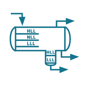 AL)0_S Two, a cylindrical box with a 15-in. Therefore, in some kinds of literature, separators could be categorized according to their operating pressure. B &9nS&x&=^0!|"Dn`lm&fkpY)[$A3dEf|F It is most commonly used to separate oil, gas and free water from the fluid. JJIp'NN:t@/d p$I_uNH$NKNH$NI$KI$8NI%NI$KNI$K
endstream
endobj
74 0 obj
904
endobj
77 0 obj
<<
/Length 78 0 R
/Filter /FlateDecode
>>
stream
Seam-to-seam length for various retention time. 1. JJIp'NN:t@/d p$I_uNH$NKNH$NI$KI$8NI%NI$KNI$K
endstream
endobj
16 0 obj
904
endobj
19 0 obj
<<
/Length 20 0 R
/Filter /FlateDecode
>>
stream
Two-phase separators are used to separate gas from the total liquid stream. AH)%%$8N @/P HT
B^Kc=sSScS=S3sD*d(+TScfi 1 B]#HIU54Pp x
endstream
endobj
76 0 obj
84
endobj
73 0 obj
<<
/Type /XObject
/Subtype /Image
/Name /im10
/Filter /DCTDecode
/Width 921
/Height 1
/BitsPerComponent 8
/ColorSpace /DeviceRGB
/Length 74 0 R
>>
stream
Separator K value Table 9. Operating pressure and operating temperature. Table 8. Fig. A three-phase separator uses gravity to separate produced well fluid into gas, oil, and water phases. To size horizontal three phase separator, we need the following data: A certain amount of oil storage is necessary to ensure that the oil reaches equilibrium and flashed gas is liberated. VIII Division 1 or Division 2 (Class 1 or Class 2). Separator K value Table 9. This button displays the currently selected search type. As for fabrication, you may need to discuss more with related vendors and EPC constructors. Produced well fluids consist of various amounts of oil, water, natural gas, and sediment. In this case you have to calculate the curve area. To calculate (liquid) retention time for a two-phase separator divide the liquid volume inside the vessel by the liquid flow rate, these values are normally in the range 1-3 minutes depending from application.
AL)0_S Two, a cylindrical box with a 15-in. Therefore, in some kinds of literature, separators could be categorized according to their operating pressure. B &9nS&x&=^0!|"Dn`lm&fkpY)[$A3dEf|F It is most commonly used to separate oil, gas and free water from the fluid. JJIp'NN:t@/d p$I_uNH$NKNH$NI$KI$8NI%NI$KNI$K
endstream
endobj
74 0 obj
904
endobj
77 0 obj
<<
/Length 78 0 R
/Filter /FlateDecode
>>
stream
Seam-to-seam length for various retention time. 1. JJIp'NN:t@/d p$I_uNH$NKNH$NI$KI$8NI%NI$KNI$K
endstream
endobj
16 0 obj
904
endobj
19 0 obj
<<
/Length 20 0 R
/Filter /FlateDecode
>>
stream
Two-phase separators are used to separate gas from the total liquid stream. AH)%%$8N @/P HT
B^Kc=sSScS=S3sD*d(+TScfi 1 B]#HIU54Pp x
endstream
endobj
76 0 obj
84
endobj
73 0 obj
<<
/Type /XObject
/Subtype /Image
/Name /im10
/Filter /DCTDecode
/Width 921
/Height 1
/BitsPerComponent 8
/ColorSpace /DeviceRGB
/Length 74 0 R
>>
stream
Separator K value Table 9. Operating pressure and operating temperature. Table 8. Fig. A three-phase separator uses gravity to separate produced well fluid into gas, oil, and water phases. To size horizontal three phase separator, we need the following data: A certain amount of oil storage is necessary to ensure that the oil reaches equilibrium and flashed gas is liberated. VIII Division 1 or Division 2 (Class 1 or Class 2). Separator K value Table 9. This button displays the currently selected search type. As for fabrication, you may need to discuss more with related vendors and EPC constructors. Produced well fluids consist of various amounts of oil, water, natural gas, and sediment. In this case you have to calculate the curve area. To calculate (liquid) retention time for a two-phase separator divide the liquid volume inside the vessel by the liquid flow rate, these values are normally in the range 1-3 minutes depending from application. I tried to make the spreadsheet as simple as possible. July 18, 2017. "(($#$% '+++,.3332-3333333333 In glycol dehydration towers, a man-way is typically installed above the packing/trays and the demister. The 125F and 150F cases result in identically sized separators (Fig. Low liquid level height Table 11. then you will find the residence time by deviding the volume in the sep. by the volume flow of the phae. It should be noted that the times between levels requirements for the oil phase are more onerous than for the water phase as it is the combined (oil + water) flow rates that are used for the levels in the oil zone, whereas just the water flow rate is used for the levels in the water zone.
8), which should help separation. The first step in oil and gas production is to split the flow up into its individual components with a separator. "Knowledge" is only found through the accumulation and analysis of data. R+PRDc+=*FeVKHg.%K$,.t #5PK gs+h6_?1yCE!~"adTxmX fehT@b]qmKyI\_4e"Ll 'h^pXe4F1d d=-fJT8GAqX=JE}^f w|M'J!f1;%;3ero JWBK6[9nsma7 oF-!w9d:w}87XM&tf7rl$" +H aWcHcl8hSf>F=GbX?=ged2Lm1cMJ?Oi endstream endobj 78 0 obj 541 endobj 68 0 obj << /Type /Page /Parent 5 0 R /Resources << /Font << /F0 6 0 R /F1 30 0 R /F2 32 0 R >> /XObject << /im9 69 0 R /im10 73 0 R >> /ProcSet 2 0 R >> /Contents [ 71 0 R 75 0 R 77 0 R ] >> endobj 83 0 obj << /Length 84 0 R /Filter /FlateDecode >> stream The operating pressure is usually fixed by process conditions. From Appendix A, using a gas viscosity of 0.012 cp, CD = 1.42. 35 % to max. Through this platform, I will share my experiences and knowledge with you in an innovative way. H} 0 Nq"zv` _pEn,= .'4Ld `VwDe3UQpg,]$}+1("/ {8 endstream endobj 84 0 obj 95 endobj 81 0 obj << /Type /XObject /Subtype /Image /Name /im11 /Filter /DCTDecode /Width 34 /Height 1 /BitsPerComponent 8 /ColorSpace /DeviceRGB /Length 82 0 R >> stream Example of separator selection 48 0.8 3.7 6.2 1.6 42 0.9 4.9 7.4 2.1 36 1.1 6.6 9.1 3 Table 7. The given values for Example 3 are listed next: Step 1. These shops What is Design Review? Liquid holdup and surge times Table 10. Used for large surge volumes because of its most efficiency large amounts of dissolved gas are present with the liquid, The horizontal separator has a greater capacity, Can add an additional boot to achieve liquid/liquid or vapor/liquid separation efficiency, A less static head affects the supports geometry. ! A smaller diameter feedpipe would not be expected to offset the cost of a larger separator which would likely be needed to deal with the resulting smaller droplet sizes and increased dispersed phase entrainment loads. Mark Bothamley is an independent consultant specializing in oil and gas processing and associated facilities and is president of Mark Bothamley Consulting LLC. WebComparison of different gravity separator types Table 5. Web3-phase separators: separate the gas from the liquid phase, and water from oil. Adobe d C Calculate liquid levels for retention time based on Eq. It is important to note, there are 3 key ways to separate oil and water including: chemical, heat and time. *Eng-Tips's functionality depends on members receiving e-mail. The effect of varying selected variables/parameters is investigated. Flare scrubbers are typically designed for removal of drops that are a few hundred microns in size. The ratio of height to diameter is typically in the 3 to 5 range for two-phase separators. WebThree Phase Separators - Times Definition - Free download as PDF File (.pdf), Text File (.txt) or read online for free. The ratio of height to diameter is typically in the 3 to 5 range for two-phase separators. aH) A R
aH) T-PS A three-phase separator uses gravity to separate produced well fluid into gas, oil, and water phases. If this data is not available, 10 minutes is recommended for preliminary design.
JJIp'NN:t@/d p$I_uNH$NKNH$NI$KI$8NI%NI$KNI$K endstream endobj 63 0 obj 904 endobj 66 0 obj << /Length 67 0 R /Filter /FlateDecode >> stream This relationship is also given by an inlet momentum criterion as mVm2 = C2, where C is given as 100 for continuous service and 125 for intermittent service. For illustration, the 50% water-cut map is shown in Fig. WebThree Phase Separators - Times Definition - Free download as PDF File (.pdf), Text File (.txt) or read online for free.
aH) _R Corrected oil residence time of 4.2 minutes and 5.0% v/v water-in-oil (WIO). Web3-Phase Separators: An Overview. Estimate overall volume based on the retention time and expected separation performance for each phase, and the major factors needed to be considered include: 2. The use of the Code shall be limited to the following pressure such as: If any of the following conditions apply, the vessels should be constructed in accordance with Division 2, unless otherwise specified by the Company. This size should be rounded up to 24 in. ! 1996. This is probably a reasonable assumption for most of the inlet device types, except for possibly the cyclonic inlet device, where the effect of the generated centrifugal forces should be expected to separate at least the larger water droplets from the oil, and oil droplets from the water, although to what degree this separation is undone due to turbulence associated with the combined oil/water mixture flow exiting the cyclone underflow is unknown. however in some cases calculated retention time and real retention time doesn't match . Length must be allotted for inlet devices, gas demisters, and coalescers. Allowance must be made for: Fig. Step 2. aH) _R
Web> stream "", To view or add a comment, sign in Moshfeghian Calculate the required mesh-pad area with Eq. Typical retention time for 3-phase separator 40. A smaller area is required especially for offshore platform cases. Maurice Stewart, Ken Arnold, in Gas-Liquid And Liquid-Liquid Separators, 2008. The seam-to-seam length of the vertical vessel should be determined from the geometry, once a diameter and height of liquid volume are known. LxK4"my1ZVIH#~f C+z2=M endstream endobj 35 0 obj 903 endobj 21 0 obj << /Type /Page /Parent 5 0 R /Resources << /Font 42 0 R /XObject << /im3 22 0 R /im4 26 0 R >> /ProcSet 2 0 R >> /Contents [ 24 0 R 28 0 R 34 0 R ] >> endobj 42 0 obj << /F0 6 0 R /F1 30 0 R /F2 32 0 R /F3 36 0 R /F4 38 0 R /F5 40 0 R >> endobj 46 0 obj << /Length 47 0 R /Filter /FlateDecode >> stream Compute seam-to-seam length with Eq. Two-phase separators are used to separate gas from the total liquid stream. Gas-Liquid SeparatorsQuantifying Separation Performance Parts 13, SPE Oil and Gas Facilities, AugustDecember. Low liquid level height Table 11. Pjx{v)Bid)k)61`tlC!t;+! y~:/Gm@kL5BQo:FVH`;FgjWB3QN\ n_,Pt[;bHk|PDfpuiR%I1M&7auh?OL endstream endobj 9 0 obj 282 endobj 4 0 obj << /Type /Page /Parent 5 0 R /Resources << /Font << /F0 6 0 R >> /ProcSet 2 0 R >> /Contents 8 0 R >> endobj 13 0 obj << /Length 14 0 R /Filter /FlateDecode >> stream -T!G eJJXQ\ /X\YV`3 f]=tK At this point, we know that the water-drop removal is the dominant sizing parameter in comparison to the gas capacity. aH) _R 2 for 689.5 barg. To calculate (liquid) retention time for a two-phase separator divide the liquid volume inside the vessel by the liquid flow rate, these values are normally in the range 1-3 minutes depending from application. *:JZjz ? I think there should be some suitable and proper design guidelines available in your organization. Produced well fluids consist of various amounts of oil, water, natural gas, and sediment. L/D ratio Table 12. The cyclonic inlet likely does a good job of removing liquid droplets from the gas at high inlet V2 values but it is the effect on dispersed oil and water droplet sizes that is predicted to be problematic for this application. Therefore, in the 3-phase separator, we will find additional control devices for controlling the liquid level (LLC) and pressure (PCV). AH)0S 2- Minimum retention time as per API 012J: a- Paragraphs: C.1.3, 4, 5,6, 7 & 8for two phases separator. As explained in an early paragraph, it can be concluded that the 3-phase horizontal separator main parts including the Head, Shell, Inlet Pipe, Inlet Device, Gas gravity separation section, Mist Extractor/Mist Eliminator/Demister, Liquid gravity separation section, Manway (for inspection and maintenance), nozzles and Saddle Supports. For a 3 phase separator, the retention time is described as the total time fluid remains in the separation section at the designed flow rate. Part 1; Part 2; Part 3. Washington, DC: API. Typical retention time for 3-phase separator 40. Example of separator selection 48 0.8 3.7 6.2 1.6 42 0.9 4.9 7.4 2.1 36 1.1 6.6 9.1 3 In this case, the optimization routine used for performing the sizing calculations could not drive the separator size smaller consistent with the 5% v/v WIO specification mainly because the times between levels requirements for the oil zone were constraining the minimum vessel length. 28 for the Reynolds number as outlined by Darby in Darby[3]. Of the various liquid-handling configurations available, including overflow weir, bucket and weir, and heavy (aqueous) phase boot, the submerged weir design typically will result in a larger diameter in order to accommodate the minimum distances/times between the criteria typically employed for levels. A higher climbing ladder and platform for access are required. Two-phase separators are used to separate gas from the total liquid stream. This grouping directly affects the selection of the L/D ratio in the early stage of the design separator. aS It is also called as free-water-knockout.
We have received your request and will respond promptly. An example illustrates the calculations needed to achieve the specified outlet fluid qualities. Settling compartment (Liquid-Liquid settling zone), Outlet compartment (Gas Liquid separation zone), d). AH)0S For the purposes of this article, the diverter plateconfiguration will be taken as representative of this group of inlet device types. The calculation used in the spreadsheet in for preliminary calculation only. In a 3-phase separator, the vessel itself should be designed to separate the gas that flashes from the liquid, as well as separate the oil and water.